
I've been searching for a while to build a very small relay bypass system for my pedals. I came up with the idea to use the internal flip flop of a NE555 chip. The most elegant solution being to use a PIC microprocessor, which is really reliable but needs some coding. Others options are to build yourself the flip flop with 2 transistors, or use a big fat CD4013 dual flip flop chip. So I came up with the schematic below:

Here are my thoughts on it:
PROS:
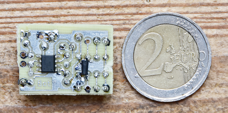
What's great is that you need very few smalls components to make it work. With a SMD NE555 and an Omron G6K-2P 9v relay, I've made it on a 2cm x 2.5cm PCB.
When you've found the right RC values for your relay (Mine are for an Omron G6K-2P 9V), it works perfectly.
CONS:
Consumption is high: 28mA when bypassed, 41mA when not bypassed and with a 2k resistance on the led. This would suck a 9V battery in 5 to 10 hours. This is no big deal with a power supply, unless your pedal is already consuming a lot, some power supplies being designed for 100mA max output, you might wanna be careful.
You need to match R1 and C1 (see my schematic) values to your relay's coil resistance. Otherwise you'll get false triggers/no trigging/fast successive on/off trigging while pushing the switch or keeping the switch pushed may bypass back the pedal after a few seconds.
A NE555 can feed up to 200mA. If the coil's resistance is too low, you may blow it.
You may download the PCB, implementation and schematics here:
PCB and implementation |
Schematic
And some pictures:


Comments
Unfortunately a G6k-2P-5V won't consume less. Let's do the math:
On a G6K-2P-9V the datasheet says the coil resistance is 795ohms, so the current flowing through it when turned on is I = U/R = 9/975 = 0.0113A. That makes a P = U*I = 0.0113*9=0.1017watts.
On a G6K-2P-5V the datasheet says the coil resistance is 237ohms, so the current flowing through it when turned on is I = U/R = 5/237 = 0.0211A. That makes a P = U*I = 0.0211*5=0.1055watts.
Which is more or less the same, but introducing a LM78L05 to lower the tension to 5V will introduce a power dissipation in the regulator of P = (9-5)*0.0211 = 0.0844watts and the total power consumption will be: P= 0.0844 + 0.1055 = 0.1899 Watts.
The better way to lower the consumption of this thing is:
- Find another 9V relay with a larger coil resistance.
- Use a TLC555 instead of a NE555, they consume 20 times less, but cost 4 times more...