
> Did we told you that we ship worldwide?
> Important notice! : Due to a large number of orders there's two weeks of delay between your order and shipment for all pedals. > UK customers : Be aware that since brexit UK customs will charge you around £49 to import a Blow! with full options.
- Details
Your privacy is important to Zorg Effects. Access to your personal data is subject to strict security controls and we will not share it with third parties.
Definition of the service
Zorg Effects is a one man company building and repairing Electronic gear for musicians, individuals or businesses. We also provide workshops or conferences for festivals, schools or associations.
Your personal data are collected and further processed only to the extent necessary to bill and send your orders. We collect: Name, surname, contact details (e-mail address; telephone number), address, country of residence, and Email exchanges. We may also collect a list of your music projects, one picture and Zorg Effects pedals you use if you whish to appear in the Artists section of the website.
Who has access to your information / who is it disclosed to?
Zorg Effects employees or interns have access to your data, which is contained in a database. Your data is stored on the server of Zorg Effects's website host: DRI. Your invoices are also stored on Zorg Effects local server for accouting and administrative purpose. Your Email exchanges with Zorg Effects are only stored on Zorg Effects's local server.
DRI has no access to the database and no responsability on the database safety. DRI is only commited in maintaining full access to the website.
No personal data is shared with third parties.
How do we protect and safeguard your information?
Only Zorg Effects CEO have access to your data. Access to the database at DRI, emails and invoices at Zorg Effects HQ are restricted with a unique ID and password.
Zorg Effects database is operated under the responsablity of the controller Gabriel Denneulin, CEO of Zorg Effects. The controller puts all his effort to ensure your data safety and compliance with EU legislation on privacy.
If you have questions or requests about the information you have submitted, please contact Zorg Effects.
Access to your personal data
You have no direct access to the data stored in our server. If you wish to modify or delete your personal data, or want to know what personal data is stored on your behalf, please contact Zorg Effects. You will receive a reply within 15 working days.
How long is your data kept?
All personal data received and stored are erased after 5 years from the database. According to the french law invoices must be kept 11 years.
Subscription to Zorg Effects mailing lists.
Zorg Effects mailing list service allows you to receive news on Zorg Effects products or events.
After clicking the "subscribe" button available on the enquiry form, your personal data (name, Email will be added to Zorg Effects's mailing lists management tool.
You can modify your data at any time via the confirmation mail that you received or in the footer of the newsletter emmited from the list. You only have the possibility to completely unregister from the system. Yo can also contact Zorg Effects to manually remove you at any time from the mailing list.
Your data is available to Zorg Effects and is kept in the mailing list database until you cancel the subscription.
- Details
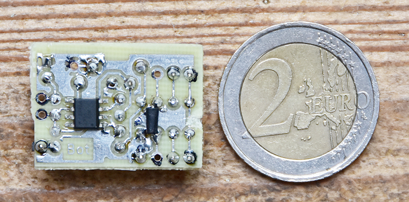
I've been searching for a while to build a very small relay bypass system for my pedals. I came up with the idea to use the internal flip flop of a NE555 chip. The most elegant solution being to use a PIC microprocessor, which is really reliable but needs some coding. Others options are to build yourself the flip flop with 2 transistors, or use a big fat CD4013 dual flip flop chip. So I came up with the schematic below:

Here are my thoughts on it:
PROS:
What's great is that you need very few smalls components to make it work. With a SMD NE555 and an Omron G6K-2P 9v relay, I've made it on a 2cm x 2.5cm PCB.
When you've found the right RC values for your relay (Mine are for an Omron G6K-2P 9V), it works perfectly.
CONS:
Consumption is high: 28mA when bypassed, 41mA when not bypassed and with a 2k resistance on the led. This would suck a 9V battery in 5 to 10 hours. This is no big deal with a power supply, unless your pedal is already consuming a lot, some power supplies being designed for 100mA max output, you might wanna be careful.
You need to match R1 and C1 (see my schematic) values to your relay's coil resistance. Otherwise you'll get false triggers/no trigging/fast successive on/off trigging while pushing the switch or keeping the switch pushed may bypass back the pedal after a few seconds.
A NE555 can feed up to 200mA. If the coil's resistance is too low, you may blow it.
You may download the PCB, implementation and schematics here:
PCB and implementation |
Schematic
And some pictures:


- Details
IntroductionIt seems that more and more wind musicians and singers plug their mics into guitars and bass pedals, forcing them to reduce the connection from XLR to jack. Unfortunately, it creates three issues. The first is that all benefits of the balanced line are lost (1). Then it's impossible to use a static microphone, because the +48v phantom alim can't be transmitted through the pedals. And lastly guitar pickups have a lot more output level than dynamics or static microphone, thus a high gain distortion becomes a slight crunch and an autowha may not trig as good as with a guitar. This is not a fatality as some expensive solutions already exists. But that's why I've decided to build a pair of pedals to solve the three issues mentioned upper. Named Just Blow! and Blow, BLOW, BLOW!!! (2), these two pedals covers the wide range of use cases for wind instruments. They should be released during the autumn 2017.(1) Loss of 6dB of signal, loss of noise rejection, maximum line length divided by 5... (2) Why such a stupid name can find an explanation here: https://en.wikipedia.org/wiki/The_National_Anthem_(Radiohead_song) The simple case : Just Blow!Just blow is made to connect a microphone in XLR and an effect loop with jacks. It features a 40dB preamp that can be internally switched to only Fx loop or both Fx and bypass signal. The phantom alim is transmitted from the mixing table to the microphone if it's been switched on on the table. A relay is used to switch smoothly the Fx loop on/off. So there's the following possibilities: XLR in => GAIN => Fx => XLR out XLR in => XLR out ou XLR in => GAIN => XLR out |

|
Two microphones case: blow, BLOW, BLOW!!!This pedal allows to use a two microphones system, either because you need to amplify a clarinet or a soprano saxophone and apply the effects on one or both microphones, or you need to use a voice and an instrument microphone and share the effect loop between them. Blow, BLOW, BLOW!!! has a bigger enclosure. One can set the input gain separately for both microphones and eventually set the phase in between them if they capture sound from the same source. On can then activate or cut each microphone and the effect loop. An internal control allows to assign or not the Fx loop to microphone 2.. The pedals gives then a lot of combinations. |

|
Some technical specs.THAT1200 and THAT1646 line drivers will be used to ensure that the full dynamic of your microphone is sent to the mixing table. Silent and transparent +40dB preamps over the whole frequency range 20Hz - 20kHz. Neutrik connections with combo XLR+Jack. |
- Details
|
|
- Details
IntroductionI’ve been working on a tremolo for a few days, and thought it could be interesting to discuss this simple effect, yet not that easy to build. If you’re a DIYer building a tremolo, I hope this document can provide some inspiration, «Do’s and don’t » and useful links. Also, for the future and current Zorglonde tremolo users, this will unveil some of its mysteries and help for a better use of it. A tremolo does a simple thing: it just changes automatically your signal's volume. Your volume goes up and down, according to a periodical waveform. But the feeling you’ll get will be different according to the rate (or frequency), the depth and the shape of that waveform. You can listen to different settings of waveform, rate and depth of a tremolo on this Zorglonde first test recording: The plan for this LONG paper, is first to give my requirements and design choices, then we’ll discuss all available possibilities to design a tremolo and in the end we’ll see the problems I encountered with the choices I made and how I solved them. I should add that this article is complementary of Coda Effects paper on his tremolo : http://www.coda-effects.com/2016/05/tap-tempo-tremolo-diy-complex-project.html This article is interesting in the fact that Coda described a philosophy quite at the opposite of the one I chose…My requirements and choices:When Dorian from Høst asked if I could build him a tremolo, I thought it would be an interesting yet simple and fast work. And I was wrong. Setting up a good oscillators took me one full week of research… But first I gave myself the following constraints :
Discussing technologies :So if you consider the electronics of a tremolo, you can breakdown the design in two:An automatic volume control, to move the signal volume up and down and a low frequency oscillator, which will create a periodical signal that will control the automatic volume control part. For the automatic volume control we can use these technologies:
Discussing automatic volume control designsDSP volume control.This one feels kind of a canon to kill a bee… That’s what Strymon does in the Flint. It’s a pertinent choice if you’re a DSP guru, and if you plan to generate complex tremolo LFO waveforms with a DSP, or if you want to have presets and tap tempo. Good also if you plan to use your DSP platform for others projects later. But starting from scratch, it’ll be a lot of work!Transconductance amplifiers volume control.This seems to me like a perfect device to achieve a tremolo. Using for example a LM13700 would provide low distortion, clean and accurate tremolo. Also it will still respond very well to oscillators into the audio frequency range (from 20Hz to 20kHz), given the right oscillator you may use also your tremolo as a ring modulator (AM modulation) ! But this was too clean for me… |
 |
Optical volume control.The optical volume control can be made using a photo-resistance such as a VTL5Cx or NSL-32. They can be used either in a tension divider or by controlling an opamp gain: |
 |
Illustration 2 shows a simple tension divider which will give:
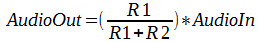 So if R1=0 there’s no audio out, and if R1 is infinite, R2 is negligible and Audio Out= Audio In.
The following schematic shows a NSL-32 optocoupler used to automatically control Audio Out:
So if R1=0 there’s no audio out, and if R1 is infinite, R2 is negligible and Audio Out= Audio In.
The following schematic shows a NSL-32 optocoupler used to automatically control Audio Out:
|
 |
| Given the NSL-32 datasheet: When its led is fully on, Ron = 500Ω, and when the led is fully off Roff=500kΩ, so we see that if we take R2 = 10kΩ we’ll get: When the NSL-32 led is on: Audio Out = 0.047 x Audio In When the NSL-32 led is off: Audio Out = 0.98 x Audio In And we can see that achieving a perfect 0V output won’t be possible… Now if we use an opamp: |
 |
In this case the opamp gain is given by:
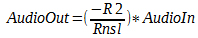 If we take R1 = 500Ω we’ll get:
When the NSL-32 led is on: Audio Out = - Audio In
When the NSL-32 led is off: Audio Out = - 0.001 x Audio In
Which is a bit better! Even if you will get better results with a VTL5C3 who gives the following values: Ron=1,5Ω, Roff=10MΩ...
But in the end, for me these devices have tons of drawbacks :
If we take R1 = 500Ω we’ll get:
When the NSL-32 led is on: Audio Out = - Audio In
When the NSL-32 led is off: Audio Out = - 0.001 x Audio In
Which is a bit better! Even if you will get better results with a VTL5C3 who gives the following values: Ron=1,5Ω, Roff=10MΩ...
But in the end, for me these devices have tons of drawbacks :
JFET used as a variable resistance volume control.The JFET used as a variable resistance can be used in the same way as optical volume control : either a tension divider or controlling an opamp gain: |
  |
If we use a J107 jFET, the same calculations as upper applies here, but with Rds on = 8Ω (Vgs = 0V) and Rds Off > 2MΩ (with Vgs > -2,5V), it’s actually better than with NSLs and similar as VTLs but 15-20 times cheaper!
(Note that jFETs values are subject to very large tolerances and these values are subject to changes, but still they’re very good!)
On some points they’re better that optical devices : they’re cheap, fast, smaller, Rohs compliant and you may or may not select them…
But they also have drawbacks :
|
 |
Transistor bias volume control.This also works with a tube. But if you make the bias of a FET preamp change by changing its source's voltage, it’ll change the gain of your preamp. The advantage of this method is that it’s fast, linear and cheap. The disadvantage is that at low gain, distortion will occur. And that’s this distortion I was thinking when saying I wanted a colourful tremolo ! Because the cool thing is that the more your volume goes down because of the LFO, the more distortion occurs… So as it happens during low volume phase of the tremolo, there’s a little psychoacoustic something happening in your brain. That’s where the magic comes from! It has also another disadvantage: it won’t work well with square waveforms. But this will be discussed later. |
 |
| The illustration below shows the distortion occurring on a 200Hz sine waveform when a 4Hz LFO of 4Vcc is applied to the FET source. As you can see it’s pretty nasty (YAY!!!): |
 |
Let’s talk about LFO’s...Doing a square waveform LFO is easy and there’s plenty of designs possibilities for a good square LFO with a huge range like from 1Hz to 1Mhz... Same for a triangle waveform LFO or a Sawtooth, which are a bit trickier than square, but still easy. On the contrary doing a good sine LFO over a wide frequency range can be a nightmare. A good sine LFO have the ability to generate a perfect sine waveform over a large frequency range. And in terms of sine, « large » can range from from 1Hz to 15Hz!Digital LFO.There are various way’s to create a digital LFO, either with a DSP, or with filtered PWM’s on a 8/16 bits microcontroller, or with filtered discrete IC’s counters… It’s the only way I know to get a very large range of frequencies available with the less distortion. Also it allows to do all kind of waveform with no limits: sine, triangle, square, sawtooth, random, half sines, step sine, etc. Check Coda Effects paper mentioned above it’s got a few examples. It’s also the only way to achieve tap tempo control of the waveform. My main concern about that was it might take too much space on the board, even if a small ATtiny could do the trick with a PWM filtered LFO... Also developing code from scratch for such a LFO would take a lot of time, even if tutorials can be found all over the Internet to reduce coding time. And last but not least, you can find already programmed ICs for a faire price, at Electric Druid for example : http://electricdruid.net/product/taplfo-tap-tempo-lfo/Dedicated integrated circuits.I’m talking about ICs like Maxim’s MAX038 or Exar’s XR2206. These circuits are a bit expensive (God the MAX038 costs 25€!!!), but are simple to use, gives low distortion waveforms over a very wide range (From 2Hz to 4kHz for the XR and 2Hz to 700Hz for the MAX). Check them datasheets for an overview of what they can do : https://www.sparkfun.com/datasheets/Kits/XR2206_104_020808.pdf But they were just too expensive for me and easily dismissed by Electric Druid LFO’s in my opinion…Wien bridge.When it comes to analog sine waveform oscillators, it’s the first idea that comes to the mind. You can get a great sine waveform out of it until you want to sweep it’s frequency. The Wien bridge is simple to understand and uses few components: |
 |
With the schematic above, if you want oscillation to happen, you’ll need R1=R2=R, C1=C2=C and R3>R4.
Then the oscillation frequency will be: 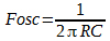 There’s a fine explanation on how it works on Wikipedia:
https://en.wikipedia.org/wiki/Wien_bridge_oscillator
The most important part of it being: “The oscillator can be viewed as a positive gain amplifier combined with a bandpass filter that provides positive feedback. […] In practice, the loop gain is initially larger than unity. Random noise is present in all circuits, and some of that noise will be near the desired frequency. A loop gain greater than one allows the amplitude of frequency to increase exponentially each time around the loop. With a loop gain greater than one, the oscillator will start.
Ideally, the loop gain needs to be just a little bigger than one, but in practice, it is often significantly greater than one. A larger loop gain makes the oscillator start quickly. A large loop gain also compensates for gain variations with temperature and the desired frequency of a tunable oscillator. For the oscillator to start, the loop gain must be greater than one under all possible conditions.
A loop gain greater than one has a down side. In theory, the oscillator amplitude will increase without limit. In practice, the amplitude will increase until the output runs into some limiting factor such as the power supply voltage (the amplifier output runs into the supply rails) or the amplifier output current limits. The limiting reduces the effective gain of the amplifier (the effect is called gain compression). In a stable oscillator, the average loop gain will be one.”
So, you can actually change the frequency of the Wien bridge a little by using a single pot on R1. But for a larger range, you’ll need to control both R1 and R2 with a dual pot. And even then it’ll rapidly go into distortion in one end, or attenuation in the other end. A x4 range (2Hz to 8Hz) is the best thing you might achieve with a doubled ganged pot and that with lots of distortion and amplitude issues.
Some suggest to use a special lightbulb instead of R3 to enhance the stability, or to use a double ganged variable capacitor for C1 and C2. Well if you’re lucky enough to have one of these exotic devices you may give a go.
But more importantly, you can enhance the Wien bridge design with an automatic gain control to achieve a better range. I didn’t had the will and the time to test it but it might be worth a test:
There’s a fine explanation on how it works on Wikipedia:
https://en.wikipedia.org/wiki/Wien_bridge_oscillator
The most important part of it being: “The oscillator can be viewed as a positive gain amplifier combined with a bandpass filter that provides positive feedback. […] In practice, the loop gain is initially larger than unity. Random noise is present in all circuits, and some of that noise will be near the desired frequency. A loop gain greater than one allows the amplitude of frequency to increase exponentially each time around the loop. With a loop gain greater than one, the oscillator will start.
Ideally, the loop gain needs to be just a little bigger than one, but in practice, it is often significantly greater than one. A larger loop gain makes the oscillator start quickly. A large loop gain also compensates for gain variations with temperature and the desired frequency of a tunable oscillator. For the oscillator to start, the loop gain must be greater than one under all possible conditions.
A loop gain greater than one has a down side. In theory, the oscillator amplitude will increase without limit. In practice, the amplitude will increase until the output runs into some limiting factor such as the power supply voltage (the amplifier output runs into the supply rails) or the amplifier output current limits. The limiting reduces the effective gain of the amplifier (the effect is called gain compression). In a stable oscillator, the average loop gain will be one.”
So, you can actually change the frequency of the Wien bridge a little by using a single pot on R1. But for a larger range, you’ll need to control both R1 and R2 with a dual pot. And even then it’ll rapidly go into distortion in one end, or attenuation in the other end. A x4 range (2Hz to 8Hz) is the best thing you might achieve with a doubled ganged pot and that with lots of distortion and amplitude issues.
Some suggest to use a special lightbulb instead of R3 to enhance the stability, or to use a double ganged variable capacitor for C1 and C2. Well if you’re lucky enough to have one of these exotic devices you may give a go.
But more importantly, you can enhance the Wien bridge design with an automatic gain control to achieve a better range. I didn’t had the will and the time to test it but it might be worth a test:
|
 |
But in the end the Wien bridge was discarded by the expression pedal requirement : there’s no double ganged pot in an expression pedal.
Phase shift LFO.The phase shifter LFO is a classic design that is used in many tremolos, specially into vintage tube amp tremolos. The cool thing about this design is that it’s done with very few cheap components, it can work with either a transistor or an AOP, though it’s understanding can be a bit complex: |
  |
In the case of the transistor version, a way to understand it simply is that if the transistor is closed, current will flow into the RC cells, in which it’ll be delayed, until it reaches the transistor base. As the RC cells charges slowly the base will slowly open the transistor and the current will slowly fade out in the RC cells causing them to discharge. And while discharging the transistor will close itself, and current will again flow through the cells and etc.
There’s a need to have a gain of 30 either with the opamp (R4= 30xR) or the transistor. With the transistor you’ll need to buffer the output if you want to attack a low impedance device with its output.
You can also add more RC cells to improve frequency stability and distortion. But if you get R1=R2=R3=R and C1=C2=C3=C, the 3 RC cell version will oscillate at: 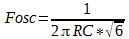 But this design has also the same drawback as the Wien Bridge: range is very limited and there’s a good amount of distortion. But still you can achieve a x4 range with a simple standard pot, dual ganged pots would let you achieve a x5 or x6 range and you get even more with a triple ganged pot. But still it has a lot of distortion and the sin waveform is far from being perfect.
Check out this page for more informations, it also show at the end how distorted the output is:
http://home.earthlink.net/~doncox/wec/Oscillators.html
I thought this design would be good enough and I spent a lot of time tweaking it, trying to match my requirements. Which revealed to be impossible, the range was always too small!
Also far better results can be achieved with a buffered or a Bubba design, but it will use more components and space. Check them out on this page:
http://sound.whsites.net/articles/sinewave.htm
But this design has also the same drawback as the Wien Bridge: range is very limited and there’s a good amount of distortion. But still you can achieve a x4 range with a simple standard pot, dual ganged pots would let you achieve a x5 or x6 range and you get even more with a triple ganged pot. But still it has a lot of distortion and the sin waveform is far from being perfect.
Check out this page for more informations, it also show at the end how distorted the output is:
http://home.earthlink.net/~doncox/wec/Oscillators.html
I thought this design would be good enough and I spent a lot of time tweaking it, trying to match my requirements. Which revealed to be impossible, the range was always too small!
Also far better results can be achieved with a buffered or a Bubba design, but it will use more components and space. Check them out on this page:
http://sound.whsites.net/articles/sinewave.htm
Quadrature oscillator.you’ll need a triple ganged pot for this one... So let's discard it rapidly...Band pass filter oscillator.This was my final choice. It’s a simple design, with few cheap components. It uses a simple mono pot which meets the requirements. The sine waveform generated has very low distortion and the range is nice for a tremolo, like x15. My design can go from 1Hz to 16Hz, but there’s a bit of signal loss in the high end (16Hz sine amplitude is half of the 8Hz sine). And anything below 1Hz is just too slow for a tremolo. |
 |
| The above schematic shows the final design with components values to achieve a 1Hz to 16Hz range and expression pedal (10k pot) implementation between exp_ring and exp_tip. It’s as simple as the Wien bridge: the right AOP is a bandpass filter which central frequency is trimmed by the RATE pot. The AOP provides unity feedback to maintain the central frequency oscillation. Diodes D3 and D4 are used to limit the oscillation amplitude to 2Vcc. Just remember that if this design works great as a LFO, it seems not to be a very good sine waveform generator in the audio range or above if a large range is needed. |
 | Designing the Zorglonde. |
| So the design choices made were : Band pass filter LFO and JFET bias. To get a square waveform LFO I simply used a saturated transistor to get the square waveform from the sine waveform. The square waveform is not perfect but it’ll do. You can add another saturated transistor to make it better if you need. Bonus, putting the led on the transistor collector will give you a led blinking at the LFO frequency: |
 |
| But then came the first issue with the bias design: When the LFO is about the top end (12Hz, 16Hz), and the more your LFO is distorted, the more low frequency noise you’ll ear. This is normal, as the bias of the FET is changed by the LFO, the LFO frequency is directly introduced in the FET’s drain output: |
 |
| So you’ll first need a heavy filtering on low frequency to minimize this noise. But if the sine LFO have some distortion it will be difficult to remove remaining higher harmonics that will pop up in the audio range. In my case 3 high pass RC cells cutting around 80Hz have been added. It’s giving the following result: |
  |
| But this problem gets worse when you switch to square LFO, as it introduce some high frequency glitches when changing from low to high state, and this even at low (like 2Hz) frequencies. And these ticks can’t be removed, or you’ll remove all you guitar sound trying to remove it! So the JFET bias, is BAD with a square waveform! In order to use the square waveform LFO, I used a JFET as a variable resistance, building a tension divider before the jFET : |
 |
| In this design, the values of the tension divider where chosen to minimize clipping in the variable resistance FET, and try to reduce the most powerful humbucker signal below 2Vcc. An interesting thing being if you change the resistance values with the switch, you can adapt the tremolo to your pickups, and gain some headroom if you have vintage single coils, or get some badass grit if you have high output pickups. The tension divider values were also chosen to minimize glitch noise. With this design glitches from the square waveform are highly diminished, but if resistance values are too high you’ll still ear it a tiny bit if your tremolo is before a high gain distortion. Then I had to keep the sine waveform LFO used as a bias volume control, cause if you wonder what happens if you route the sine LFO to the jFET used in the tension divider, here’s what you get: awful linearity. |
 |
Drawback of this design is that I had to use a charge pump circuit to create -9v out of the 9v power input. The oscillator won’t work with 0-9v, and I needed a negative tension on the FET as a variable resistance grid.
Conclusion.As a conclusion, let's just stare at the output of this tremolo. Depth setting is the same for all curves, except the pulse curve where it's a bit deeper.For the sine waveform. |
    |
For the square waveform. |
   |
- Details
| William, who plays the trumpet in Tanidual, Bdc LaBelle and Walter Sextant, was searching something to make his trumpet sound fatter. It seems the mission is accomplished with a Zorgtaver and a Love philter. In William's test extract below he's using a Zorgtaver plugged into the Love Philter. A moogerfooger ring mod LFO is sent to the Love Philter's CV input to command the cut off frequency: |
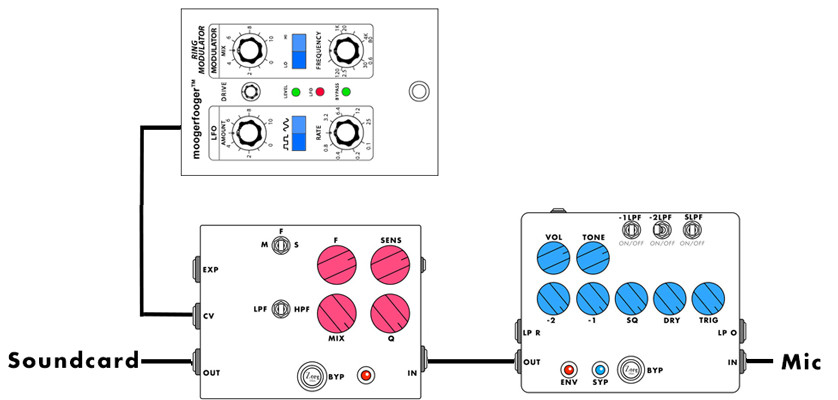
|
| And that's the final result: |
- Details
| Kevin who's playing bass guitar in la Marmaille and Acropolis Bye Bye, sent me a few presets for the Glorious Basstar pedal. Here they are: |
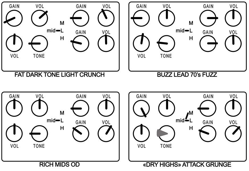
|
| Then I recorded them so that we can hear how they sound.The Basstar is plugged directly in my soundcard. You may plug your soundcard in your amp to get the -almost- final result! |
- Details
| First made for guitar, this legendary fuzz has been also made for bass. The result is a very dark fat fuzz with tone of bass and subs, but also very little bite and attack. Some like it, others don't and this article is made for the latest who own one and don't know what to do with it. I'm going to discuss a few very simple mods that can transform it into something funnier. This article is based on this mods list and plan of the big muff version for guitar available here. I'll detail here the following mods: high end roll off mod, diode mod, tone stack mod, and bias mod, this later is not listed on the website above. And before all, here's the result: |
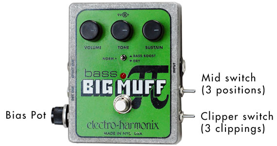
|
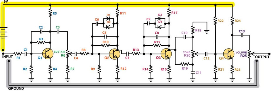
The schematic.During all the article we will use the schematic below. It's from the guitar version but you'll find it also in the bass version along with the "dry" and "bass boost" circuits added for the bass version. The components numbering is not the same in the pedal also, and the diodes are replaced by transistors like diodes. We don't need the "dry" and "bass boost" circuits for this article |
|
High end roll off mod.It's a useless mod on the bass version... On the guitar version changing caps C5 and C8 will change the amount of high end treble generated by the distortion. On the bass version the C5, C8 are unmarked and seems to be 470pF. They form a low pass filter with resistances R11 and R17 who are 12k. The cut off frequency for the bass version is thus F = 1/(2xPixRxC) = 1/(2 x 3.14 x 0.00000000047 x 12000)= 28 218Hz. So the bass version let all the treble pass (before you remove them with the "tone" knob). Don't bother removing them to get more bite. Also removing C2 improves a tiny bit the frequency roll of after 4kHz. But it has very little changes on the overall sound. |
Diodes mods. |
|
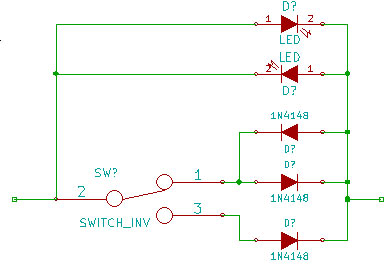
| This mod replaces diodes D1 to D4 by different diodes. Changing the diode type changes the distortion grain a bit an the dynamic a lot. In our case we needed first to remove the two transistors-like pairs of diodes (MMBD4148) to replace them by yellow leds. Fortunately there's a space left unused on the board for the leds. The a 3 position switch with 1N4148 on it allows to choose between 3 modes: 2x leds, 1 diode + 1 led. 2 diodes. The schematic of the mod is given on the right. When the switch is in the middle position only the leds works. In the low position, the single diode in turned on and, due to its threshold, replace one of the led. In the high position both leds are replaced by the 1N4148. |
|
| Here's the result for the 3 positions: |
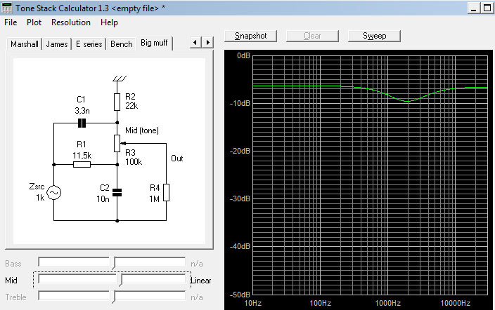
Tone stack mod.The base tone stack and it's frequency response is the following: |
|
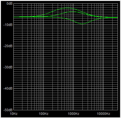
| This mods consist simply in adding a cap in parallel of C10 (on the upper schematic). With a 3 position switch and two caps of 10nF and 28nF, we respectively get the following curves: the original curve, one a small bump at 1kHz, and one with a bump at 600Hz: |
|
| And the audio result: |
Bias mod.This mod is not mentioned is the mod website and is probably the most exciting. We're going to change the bias of the output stage (Q4 transistor) with a 1M pot in parallel of R22. Here's the result for different pot's positions: |
Conclusion.With all these mods we made this pedal a lot funnier, with more sound possibilities and "bass synth"-like sounds thanks to the bias pot! And here the inside: |
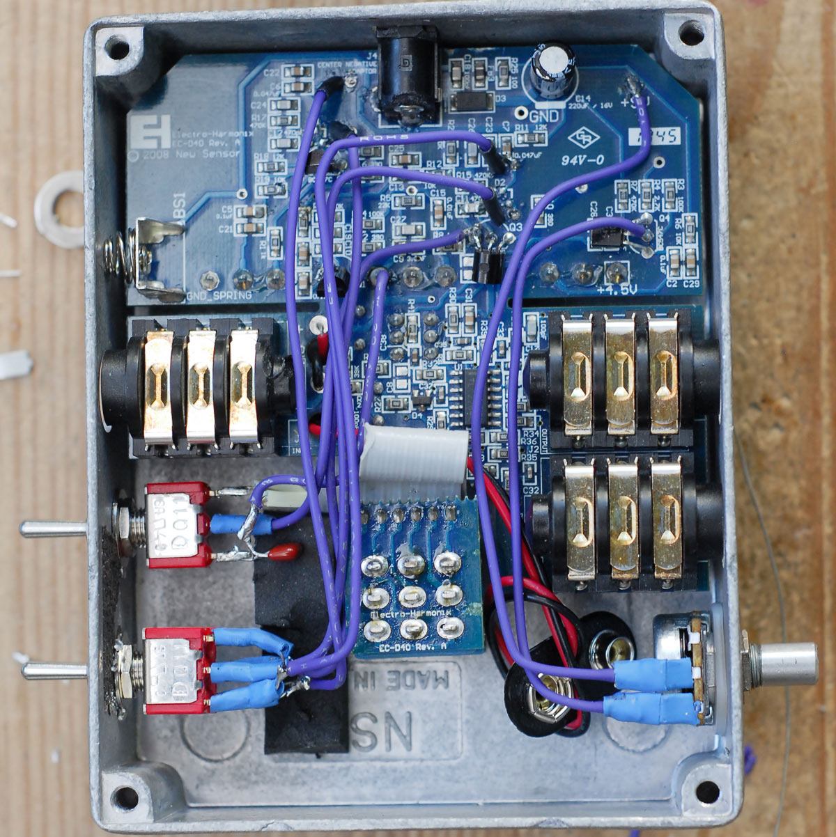
|
- Details
| These pedals are now useless to me and may be helpful to someone else. They've all been assembled by me and are all in working conditions. All must be powered by external power supply. No batteries. I'm shipping worldwide. Please contact me using the contact form of the website if you're interested! |
|
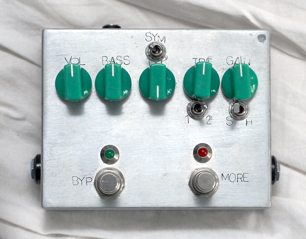
Zorgverdrive Deluxe Prototype #2 This is the 2nd prototype of the Zorgverdrive Deluxe (There's been 3 prototypes, and I'm keeping the 3rd). Unlike the final version it has no mid knob and no volume internal trimpot. (But there's the gain trimpot). The switch 1/2 is useless. The rest is in perfect condition. Sold |
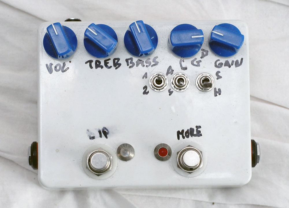
| Zorgverdrive Deluxe Prototype #1 This is the 1st prototype of the Zorgverdrive Deluxe. Unlike the final version it has no mid knob and no volume internal trimpot. (But there's the gain trimpot). The switch 1/2 is useless. It makes distortion, but is not as cool as the prototype #2. Writings can be removed with acetone or alcohol to make a cleaner design. Price - without shipping costs: 40€ |
|
|
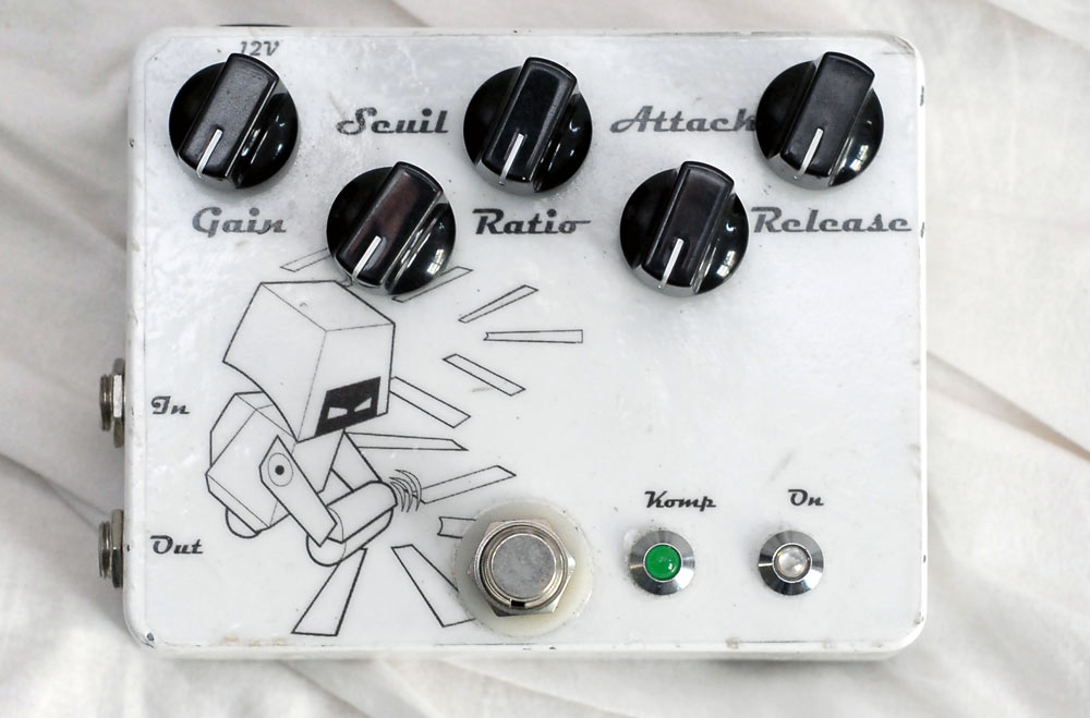
Optical compressor Warning: Works only with 12V My first compressor with a lot of features. It's a DIY pedal version of the What compressor. The optic cell is indeed a VTL5C9. It's awesome and works perfectly! Price - without shipping costs: 80€ |
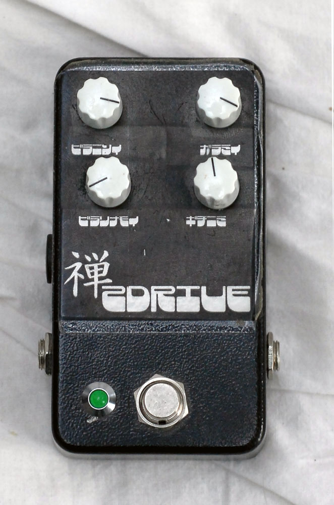
| Zendrive Clone A kit from musikding: The Zendrive. Price - without shipping costs: 20€ |
|
- Details
My dear friend Alex told me I should mention what kind of gear I'm using for my Youtube videos.
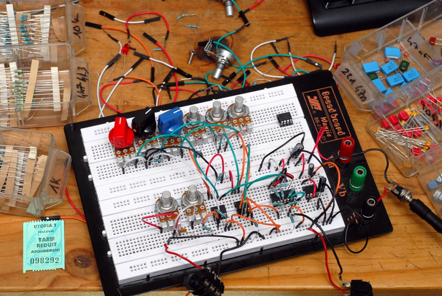
So, here it goes for the fetishist shit list; I'll go in detail through all the gear I'm using in the videos, and then for prototyping/designing/testing my pedals.
For the videos: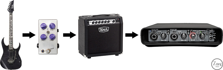 Unless mentioned, the picture above shows my recording set-up for Youtube videos. That means: An Ibanez J-Custom, the pedal, a Koch Studiotone, and a TC Impact twin. Then it goes into my DAW where absolutely nothing is done apart from gain settings. You should notice there's no microphone involved: because I've got neighbors, you know... So I'm using the Studiotone's red box recording output. The red box is a passive analogue microphone and speaker simulator. But it's also a load box, so I can put a fair amount of volume, cut the amp's speaker and record at low volume. I use to have a red bean shaped device who could have done the same, but I like the red box way better... Oh and the amp set-up is clean channel, flat Eq.
During pedal design:Guitars:
|
- Details
After having discussed with many bass players, and tested a few pedals (Glue Fuzz, MetalFest, Zorgverdrive deluxe) on bass. I tried to prototype a multiband distortion. The idea is the following: I cut the signal in three parts: bass, mids, trebles. Each part goes into it's own gain stage with a pair of clippers. One can thus change the amount of gain separately on each part. Each part generates different grain of distortion (the grain of the bass part is very cold and acid, whereas the grain of the treble part is more tubby). Then all three signals are blended back together at your will. With such a process, one can get heavy distortions without loosing precision, or decide to loose precision... So, it's pretty funny!
For now the following controls are mandatory:
|
 |
Page 1 of 2